logic gate schematic
circuit design - Logic gates in a schematic - Electrical Engineering. 17 Pictures about circuit design - Logic gates in a schematic - Electrical Engineering : How to Create a Logic Gate Diagram | Edraw, How are logic gates designed? - Electrical Engineering Stack Exchange and also FAST XOR-XNOR CIRCUIT.
Circuit Design - Logic Gates In A Schematic - Electrical Engineering
 electronics.stackexchange.com
logic schematic gates
Logic Gate Diagrams Aka Circuits - YouTube
 www.youtube.com
VHDL Tutorial: Learn By Example
 esd.cs.ucr.edu
alu tutorial synthesis labs esd multiplier schematic
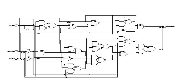
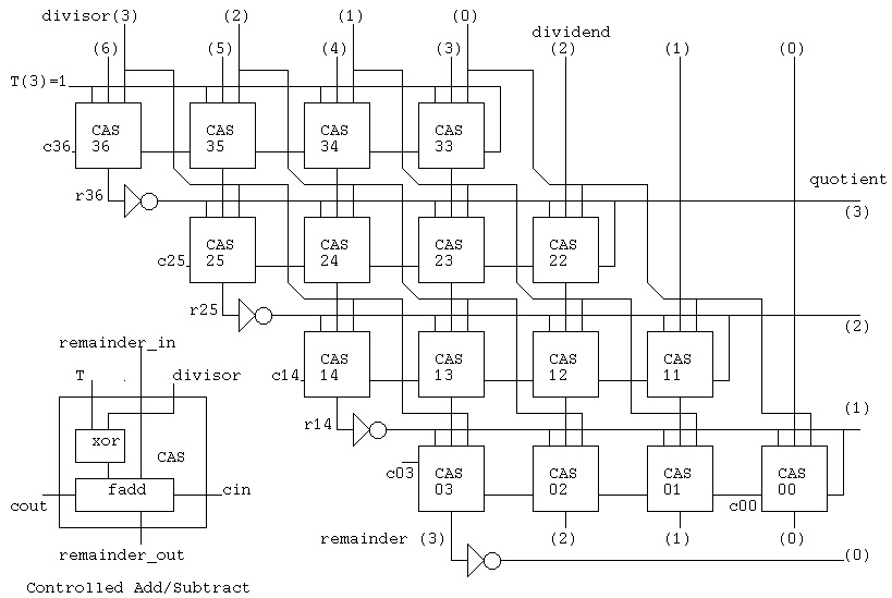
VHDL Samples
 www.csee.umbc.edu
vhdl divider bit schematic samples code example parallel cas simple subtract test csee umbc portal edu help bench
Logic Gate Wiring Diagram
 sometimesawitch.blogspot.com
How Are Logic Gates Designed? - Electrical Engineering Stack Exchange
 electronics.stackexchange.com
schematic logic gates designed gate circuitlab created using
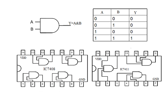
Digital Electronics - Basic Truth Tables
 www.technologystudent.com
gate logic inverter gates tables output electronics basic digital
Basic Gate Function | Digital Integrated Circuits | Electronics Textbook
 www.allaboutcircuits.com
Converting Truth Tables Into Boolean Expressions | Boolean Algebra
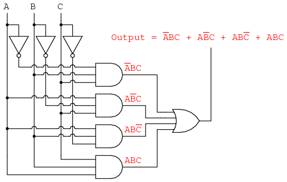 www.allaboutcircuits.com
truth output boolean digital schematic input tables expressions logic circuit gate expression algebra table function relay into electronics circuits sum
Transistors - Understanding A CMOS Logic Gate With Strange Details
 electronics.stackexchange.com
schematic logic cmos understanding strange gate circuitlab circuit created using
How To Create A Logic Gate Diagram | Edraw
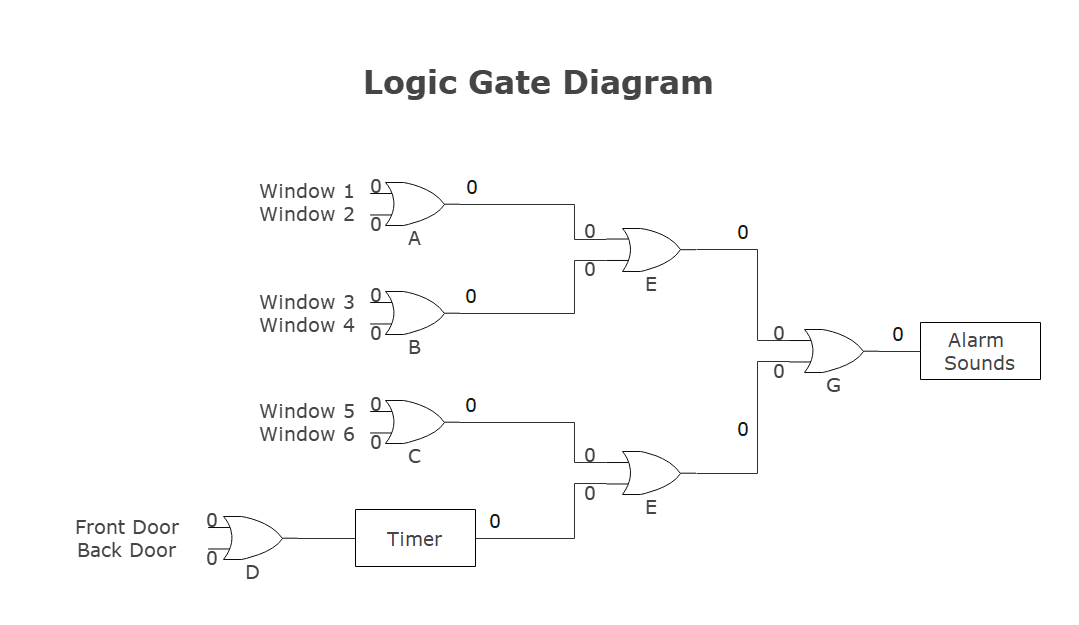 www.edrawsoft.com
example2 adder
Solved: For The Logic Gate Circuit Shown In Figure 4-30:a. Dete
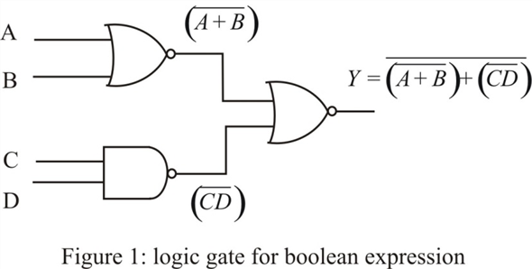 www.chegg.com
gate shown figure logic circuit nor equa determine
FAST XOR-XNOR CIRCUIT
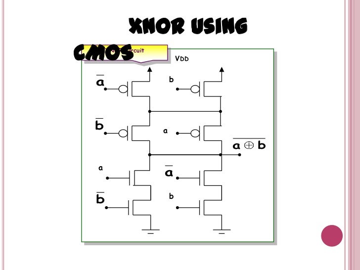 www.slideshare.net
xnor cmos xor
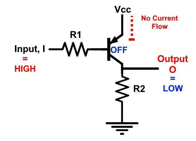
Digital Logic NOT Gate (Inverter), Its Symbols, Schematics & IC Details
 allabouteng.com
gate logic digital pnp schematic ic case inverter symbols its
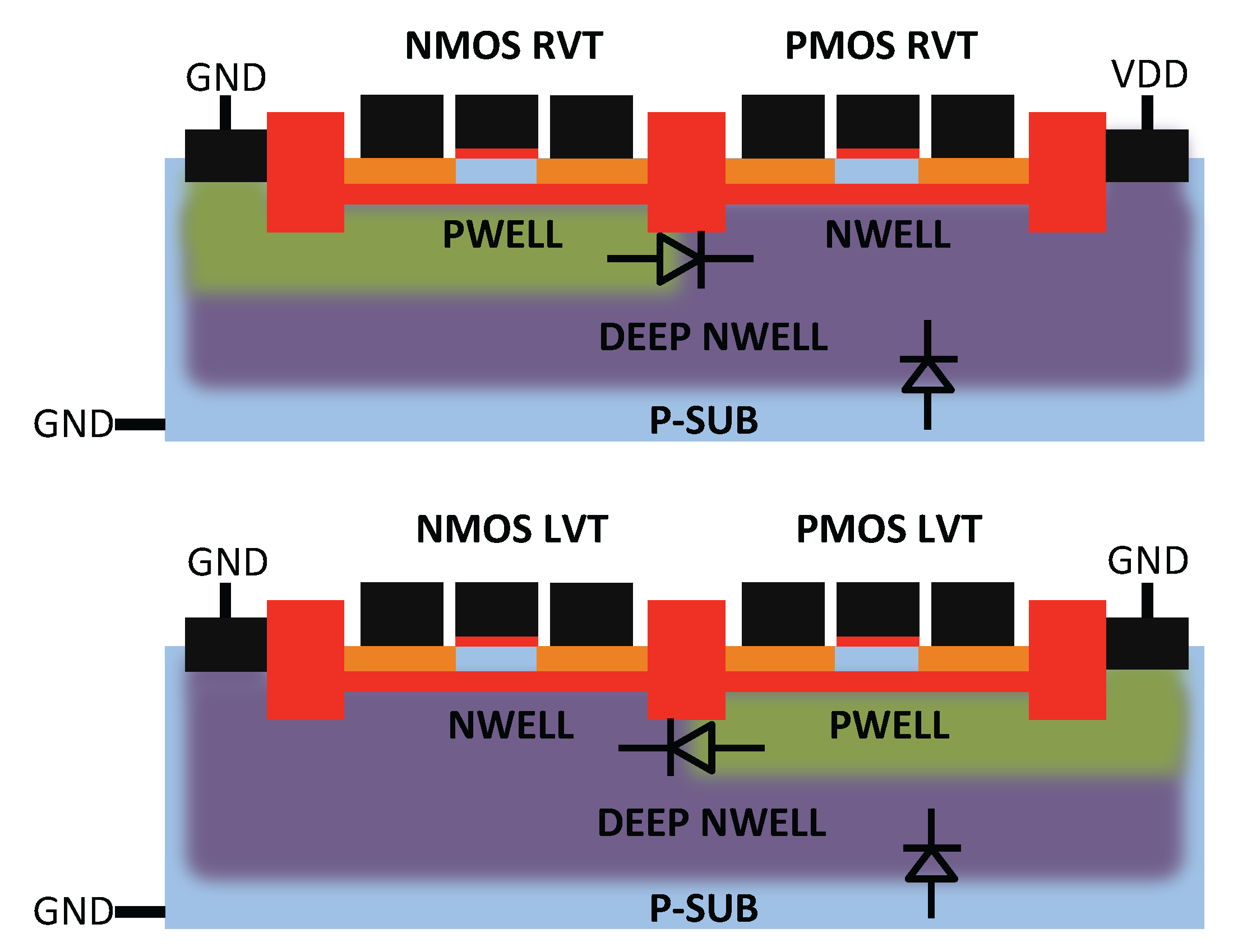
JLPEA | Free Full-Text | Study Of Back Biasing Schemes For ULV Logic
 www.mdpi.com
fdsoi gate jlpea body schematic study
Logic Gates Diagram And Truth Table - Wiring Diagram Schemas
 wiringschemas.blogspot.com
truth
How To Design 2 Input XOR Gate Using Dynamic CMOS Logic In VLSI DESIGN?
 www.researchgate.net
xor cmos vlsi dynami
How are logic gates designed?. Logic gate diagrams aka circuits. Logic gates diagram and truth table